- Manuals
- NX OM
- NX SM
- New
- Top
- Sitemap
- Search
![]()
Lexus NX: Taillight Relay Circuit
DESCRIPTION
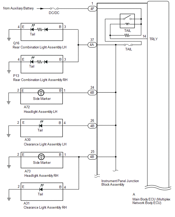
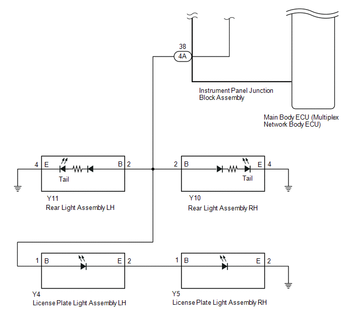
Illumination of the taillights and license plate light is controlled by the main body ECU (multiplex network body ECU).
WIRING DIAGRAM
CAUTION / NOTICE / HINT
PROCEDURE
| 1. | PERFORM ACTIVE TEST USING TECHSTREAM (TAILLIGHT RELAY) |
(a) Using the Techstream, perform the Active Test.
Click here .gif)
Body Electrical > Main Body > Active Test
| Tester Display | Measurement Item | Control Range | Diagnostic Note |
|---|---|---|---|
| Taillight Relay | Taillight relay | ON or OFF | - |
Body Electrical > Main Body > Active Test
| Tester Display |
|---|
| Taillight Relay |
| Result | Proceed to |
|---|---|
| Taillights, license lights and side marker lights come on | A |
| Taillights, license lights and side marker lights do not come on | B |
| B |
.gif) |
| 2. | CHECK HARNESS AND CONNECTOR (INSTRUMENT PANEL JUNCTION BLOCK ASSEMBLY - BATTERY) |
(a) Disconnect the instrument panel junction block assembly connector.
| (b) Measure the voltage according to the value(s) in the table below. Standard Voltage:
|
|
.png)
| NG | .gif) | REPAIR OR REPLACE HARNESS OR CONNECTOR |
| OK |
| |
| 3. | INSPECT INSTRUMENT PANEL JUNCTION BLOCK ASSEMBLY |
(a) Remove the instrument panel junction block assembly.
Click here
(b) Remove the instrument panel junction block assembly.
Click here
(c) Measure the voltage according to the value(s) in the table below.
Standard Voltage:
| Tester Connection | Condition | Specified Condition |
|---|---|---|
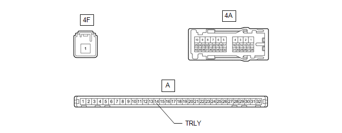
| 4A-37 - Battery negative (-) terminal | Battery voltage applied between terminals 4F-1 and A-14 (TRLY) | 11 to 14 V |
| Battery voltage not applied between terminals 4F-1 and A-14 (TRLY) | Below 1 V | |
| 4A-38 - Battery negative (-) terminal | Battery voltage applied between terminals 4F-1 and A-14 (TRLY) | 11 to 14 V |
| Battery voltage not applied between terminals 4F-1 and A-14 (TRLY) | Below 1 V | |
| 4B-24 - Battery negative (-) terminal | Battery voltage applied between terminals 4F-1 and A-14 (TRLY) | 11 to 14 V |
| Battery voltage not applied between terminals 4F-1 and A-14 (TRLY) | Below 1 V | |
| 4B-25 - Battery negative (-) terminal | Battery voltage applied between terminals 4F-1 and A-14 (TRLY) | 11 to 14 V |
| Battery voltage not applied between terminals 4F-1 and A-14 (TRLY) | Below 1 V | |
| 4B-25 - Battery negative (-) terminal | Battery voltage applied between terminals 4F-1 and A-14 (TRLY) | 11 to 14 V |
| Battery voltage not applied between terminals 4F-1 and A-14 (TRLY) | Below 1 V |
READ NEXT:
 Power Source Circuit
DESCRIPTION The main body ECU (multiplex network body ECU) receives IG signals and supplies power to the headlight ECU sub-assembly via the H-LP relay. WIRING DIAGRAM CAUTION / NOTICE / HINT NOTICE:
Cornering Light Circuit
DESCRIPTION The illumination of the fog light assembly (cornering light) is controlled by the headlight ECU sub-assembly. WIRING DIAGRAM CAUTION / NOTICE / HINT NOTICE: The light system (for Tripl
SEE MORE:
Replacement
REPLACEMENT PROCEDURE 1. REMOVE NO. 1 ENGINE UNDER COVER Click here 2. DRAIN COOLANT (for Inverter Coolant) NOTICE: Collect the drained coolant and measure its volume to establish a benchmark. When adding coolant, make sure to add more coolant than the measured amount. (a) Remove the inverter re
Terminals Of Ecu
TERMINALS OF ECU CHECK MULTIPLEX NETWORK DOOR ECU (a) Disconnect the Y26 and Y27 multiplex network door ECU connectors. (b) Measure the voltage and resistance according to the value(s) in the table below. Terminal No. (Symbol) Wiring Color Terminal Description Condition Specified Conditi
© 2016-2021 Copyright www.lexunx.com
Posted by: emiliothoningoau.blogspot.com
Source: https://www.lexunx.com/taillight_relay_circuit-2384.html
